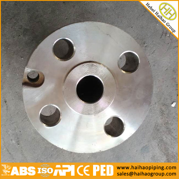
ASME B16.36 Standard Specification For Orifice Flanges
ASME B16.36-2015 standard covers pressure-temperature ratings,materials,dimensions, tolerances, testing, and making of flanges (similar to those covered in ASME B16.5) that have orifice pressure differential connections. Coverage is limited to the following:
- a) welding neck flanges Classes 300, 600, 900, 1500, and 2500.U.S. Customary units are presented in Mandatory Appendix I.
- b) slip-on and threaded Class 300.
- c) welding neck flanges Class 400 in U.S. Customary units in Mandatory Appendix II.
ASME B16.36-2015 Standard Specification For Orifice Flanges
- 1.SCOPE
- 2.GENERAL
- 3.PRESSURE–TEMPERATURE RATINGS
- 4.MATERIAL
- 5.SIZE
- 6.MARKING
- 7.FLANGE FACING FINISH
- 8. GASKETS FOR RAISED FACE FLANGES
- 9.PRESSURE TAPS
- 10.JACK SCREW PROVISION
- 11.FLANGE DIMENSIONS
- 12.FLANGE THREADS
- 13.TOLERANCES
Orifice Flange
1.SCOPE
This standard covers pressure-temperature ratings,materials,dimensions,tolerances,testing,and making of flanges (similar to those covered in ASME B16.5) that have orifice pressure differential connections. Coverage is limited to the following:
(a) welding neck flanges Classes 300, 600, 900, 1500, and 2500. U.S. Customary units are presented in Mandatory Appendix I.
(b) slip-on and threaded Class 300.
(c) welding neck flanges Class 400 in U.S. Customary units in Mandatory Appendix II.
2.GENERAL
2.1 References
Codes, standards, and specifications containing provisions to the extent referenced herein constitute requirements of this Standard. These reference documents are listed in Mandatory Appendix III.
2.2 Quality Systems
Nonmandatory requirements relating to the product manufacturer’s Quality System Program are described in Nonmandatory Appendix A.
2.3 Relevant Units
This Standard states values in both SI(Metric) and U.S. Customary units. As an exception, diameter of bolts and flange bolt holes are expressed in inch units only. These systems of units are to be regarded separately as standard. Within the text, the U.S. Customary units are shown in parentheses or in separate tables. The values stated in each system are not exact equivalents; therefore, it is required that each system of units be used independently of the other. Except for diameter of bolts and flange bolt holes, combining values from the two systems constitutes nonconformance with the standard. Except for Class 400 the values in U.S. Customary units are in Mandatory Appendix I. The main text of this Standard does not contain requirements for Class 400 welding neck flange; however, Mandatory Appendix II does contain requirements for this class, expressed in U.S. Customary units only.
2.4 Convention
For determining conformance with this Standard, the convention for fixing significant digits where limits(maximum and minimum values) are specified, shall be as defined in ASTM E 29. This requires that an observed or calculated value be rounded off to the nearest unit in the last right-hand digit used for expressing the limit. Decimal values and tolerances do not imply a particular method of measurements.
2.5 Denotation
2.5.1 Pressure Rating Designation
(a) Class, followed by a dimensionless number, is the designation for pressure–temperature ratings as follows: Classes 300 600 900 1500 2500.
(b) Class 400 is retained in the U.S. Customary tables.
2.5.2 Sizes. NPS, followed by a dimensionless number, is the designation for the nominal flange size. NPS is related to the reference nominal diameter, DN, used in international standards. The relationship is, typically, as follows:
| NPS | 1 | 1½ | 2 | 2½ | 3 | 4 |
| DN | 25 | 40 | 50 | 65 | 80 | 100 |
GENERAL NOTE: For NPS ≥ 4,the related DN p25×(NPS).
2.6 Service Conditions
Criteria for selection of materials suitable for the particular fluid service are not within the scope of this Standard.
3.PRESSURE–TEMPERATURE RATINGS
The pressure-temperature ratings,including all use recommendations and limitations,and the method of rating given in ASME B16.5 apply to these flanges.
4.MATERIAL
4.1 General
(a)Flange materials shall be in accordance with the requirements of ASME B16.5.Flanges shall be manufactured as one piece in accordance with the applicable materials specification.Assembly of multiple pieces into the finished product by welding or other means is not permitted by this Standard.
(b)For materials manufactured to editions of the material specification other than those listed in Mandatory Appendix Ⅲ of ASME B16.5,refer to para.4.3.
4.2 Bolting
Bolting material recommendations are given in ASME B16.5.For materials manufactured to editions of the material specification other than those listed in Mandatory Appendix Ⅲ of ASME B16.5,refer to para.4.3.
4.3 Materials Manufactured to Other Editions
Materials may meet the requirements of material specification editions other than those listed in Mandatory Appendix Ⅲ of ASME B16.5,provided
(a) the materials are the same specification,e.g.,grade,type,class,or alloy,and heat-treated conditions,as applicable
(b) the flange manufacturer certifies that the requirements of the edition of the specification listed in Mandatory Appendix Ⅲ of ASME B16.5 have been met.
4.4 Plugs
Pressure-retaining plugs shall conform to ASME B16.11, unless otherwise agreed between purchaser and manufacturer. Plug material shall be at least as corrosion resistant as the corresponding flange material.
5.SIZE
Orifice flange sizes are indicated by the nominal pipe size to which they are attached.Only those listed in Tables 1 through 5,Tables I-1 through I-5,and Mandatory Appendix II are considered standard.
6.MARKING
Flanges shall be marked as required in ASME B16.5.For welding neck flanges only,the bore diameter shall be marked.
7.FLANGE FACING FINISH
The finish of contact faces shall conform to the requirements of ASME B16.5.
8. GASKETS FOR RAISED FACE FLANGES
8.1 Gasket Thickness
Flange dimensions are based on the use of 1.5 mm (0.06 in.) thick gaskets.
8.2 Flange Gaskets Requiring Dimensional Changes
When the location of the pressure tap with respect to the orifice plate is critical to the service and metering conditions,its location may be altered to accommodate other than 1.5 mm (0.06 in.) thick gaskets or ring-type joint gaskets whose thickness may vary from that listed in in Tables 2 through 5 or those listed in Tables I-2 through I-5 or Mandatory Appendix II.
The alteration of location may also be accomplished by the removal of 2 mm (0.06 in.) from the raised face of the flange.If an original 2 mm (0.06 in.) high raised face is removed,the user is cautioned to limit the outside diameter of the gasket or orifice plate to the tabulated R dimension.
9.PRESSURE TAPS
9.1 General
Each orifice flange shall be provided with two pressure tap holes extending radially from the outside diameter of the flange to the inside diameter of the flange.Corner taps may be used on NPS 1 1⁄2 and smaller if space permits. See Fig. 1.
For ring joint flanges listed in Tables 2 through 5, Tables I-1 through I-5, and Mandatory Appendix II where radial taps will interfere with the ring groove,angular meter taps,as illustrated in Fig. 2,will be required.Each pressure tap hole shall be equipped with a pipe plug.
9.2 Location
9.2.1 Measurement. The 24 mm (0.94 in.) dimension for raised face and 19 mm (0.75 in.) for ring joint shall be measured at the bore.
9.2.2 Identification. For ring joint flanges requiring alteration of pressure tap location due to interference with the ring groove other than methods provided in this Standard,such alteration shall be identified per agreement between purchaser and manufacturer.
9.3 Pipe Connection
Unless otherwise specified, pressure tap holes may be either tapped 1/2 NPT in accordance with ASME B1.20.1 or 1⁄2 NPS socket connection in accordance with ASME B16.11.
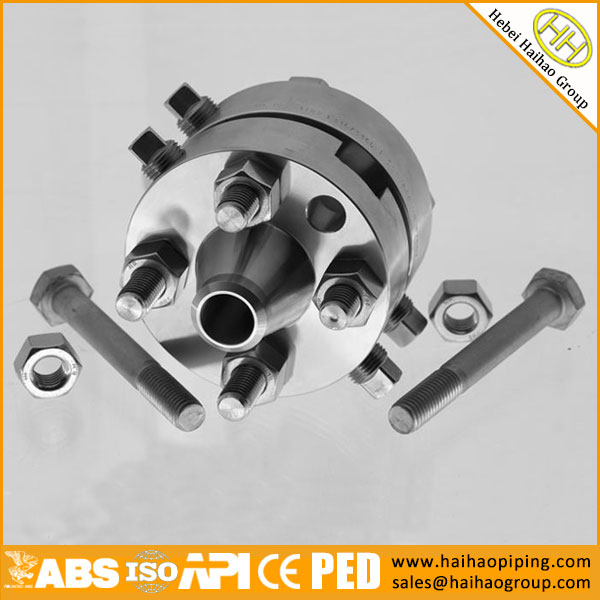
10.JACK SCREW PROVISION
10.1 Location
Each flange shall have a machine bolt mounted in a hole drilled on the flange bolt circle centerline at 90 deg from the pressure taps,for use as a jack screw.The machine bolt shall be regular with one heavy hex nut. See Fig. 3.
10.2 Slot for Nut
A slot shall be provided in the flange 2 mm (0.06 in.) wider than the width across flats of the nut. The depth of the slot shall admit the nut so that there is no interference with the joining of the flanges when bolted together without orifice plate.
10.3 Tapped Hole
As an alternative to para. 10.2, a tapped hole may be provided and the hex nut omitted when agreed on between the purchaser and the manufacturer.
11.FLANGE DIMENSIONS
Dimensions are listed in Tables 1, 2, 3, 4, and 5, for metric, and Tables I-1, I-2, I-3, I-4, and I-5, and Mandatory Appendix II for U.S. Customary.
12.FLANGE THREADS
Threaded flanges shall have an American National Standard taper pipe thread conforming to ASME B1.20.1.
(a) The thread shall be concentric with the axis of the flange. Variations in alignment shall not exceed 5 mm/M (0.06 in./ft).
(b) The flanges are made with counterbores at the back of the flange and the threads shall be chamfered to the diameter of the counterbore at an angle of approximately 45 deg with the axis of the thread to afford easy entrance in making a joint. The counterbore and chamfer shall be concentric with the thread.
(c) In order to permit the pipe to be inserted to the face of the flange, the threads should have full root diameters through to the face of the flange, or shall have a counterbore at the face of the flange.
(d) The gaging notch of the working gage shall come flush with the bottom of the chamfer in all threaded flanges and shall be considered as being the intersection of the chamfer cone and the pitch cone of the thread.This depth of chamfer is approximately equal to one-half the pitch of the thread.
(e) The maximum allowable thread variation is one turn large or small from the gaging notch.
13.TOLERANCES
Tolerances on all dimensions shall be as shown in ASME B16.5 except for those shown below.
13.1 Pressure Tap Location
Tolerance on location of center of pressure tap hole1 from flange face shall be
(a) ±0.5 mm (±0.02 in.) for flanges smaller than NPS 4
(b) ±0.8 mm (±0.03 in.) for flanges NPS 4 and larger
13.2 Bore Diameter
Bore diameter tolerance (welding neck flanges only) is ±0.5% of nominal value.
Note: 1 See para. 9.2.
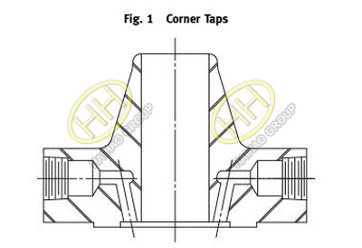
ASME B16.36-2015 Standard Orifice Flange Corner Taps
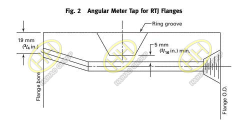
ASME B16.36-2015 Standard Orifice Flange Angular Meter Tap for RTJ Flanges
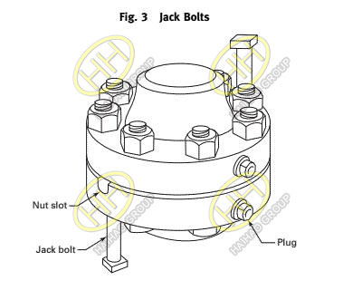
ASME B16.36-2015-Standard Orifice Flange Jack Bolts
Related:
- ASME B16.36 Class 300 Orifice Flanges,Welding Neck,Threaded,and Slip-On Dimensions
- ASME B16.36 Class 600 Orifice Flanges,Welding Neck Dimensions
- ASME B16.36 Class 900 Orifice Flanges,Welding Neck Dimensions
- ASME B16.36 Class 1500 Orifice Flanges,Welding Neck Dimensions
- ASME B16.36 Class 2500 Orifice Flanges,Welding Neck Dimensions