ASME B16.36 Class 300 Orifice Flanges,Welding Neck,Threaded,and Slip-On Dimensions
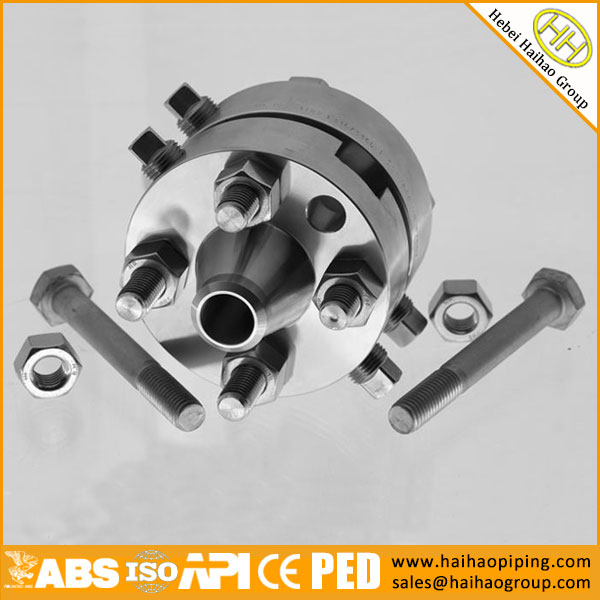
Haihao Group manufacture & supply orifice flanges according to ASME B16.36-2015 standard,the product material can be carbon steel,stainless steel,alloy steel.The nominal size for orifice flanges are 1″-24″.
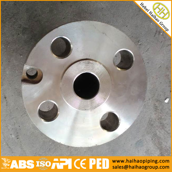
1inch SS304 RF Orifice Flange
ASME B16.36-2015 Class 300 Orifice Flanges,Welding Neck,Threaded,and Slip-On Dimensions
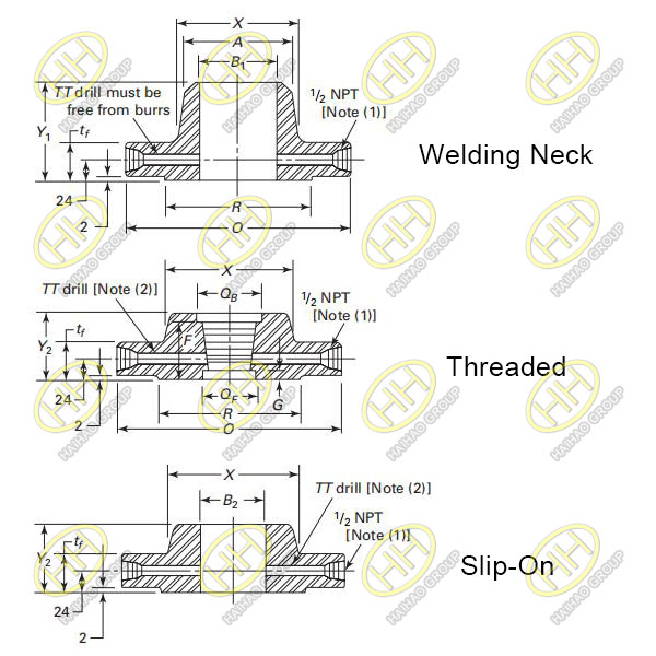
ASME B16.36 2015 Class 300 Orifice Flanges Welding Neck Threaded and Slip On
| Nominal Pipe Size | Outside Diameter of Raised Face,R | Outside Diameter of Flange,O | Minimum Thickness of Flange,tf | Length Through Hub | Diameter of Hub,X | Hub Diameter Beginning of Chamfer(W.N.),A | Diameter of Counterbore | Counterbore Depth(From Face) | Bore |
Diameter of Pressure Connection, |
Drilling Template | Bolt Length[(3),(4)] | ||||||||||||||||||||||||
| in millimeters | in inches | in millimeters | in inches | in millimeters | in inches | Slip-On and Threaded,Y2
in millimeters |
Slip-On and Threaded,Y2
in inches |
Weld Neck,Y1
in millimeters |
Weld Neck,Y1
in inches |
in millimeters | in inches | in millimeters | in inches | Back,QB
in millimeters |
Back,QB
in inches |
Face,QF
in millimeters |
Face,QF
in inches |
F
in millimeters |
F
in inches |
G
in millimeters |
G
in inches |
Slip-On,B2
in millimeters |
Slip-On,B2
in inches |
Weld Neck,B1 | in millimeters | in inches | Bolt Circle
in millimeters |
Bolt Circle
in inches |
Number of Holes | Diameter of Holes | Diameter of Bolts | Machine Bolts
in millimeters |
Machine Bolts
in inches |
Stud Bolts
in millimeters |
Stud Bolts
in inches |
|
| 1 | 50.8 | 2.00 | 125 | 4.88 | 36.6 | 1.44 | 46 | 1.81 | 81 | 3.19 | 54 | 2.12 | 33.4 | 1.32 | 35.8 | 1.41 | 33.0 | 1.30 | 36.5 | 1.44 | 19.0 | 0.75 | 34.5 | 1.36 | See Note (5). | 6.4 | 1/4 | 88.9 | 3.50 | 4 | 11/16 | 5/8 | 115 | 4.50 | 125 | 5.00 |
| 1½ | 73.0 | 2.88 | 155 | 6.12 | 36.6 | 1.44 | 46 | 1.81 | 84 | 3.31 | 70 | 2.75 | 48.3 | 1.90 | 50.5 | 1.99 | 48.0 | 1.89 | 37.3 | 1.47 | 18.3 | 0.72 | 49.5 | 1.95 | 6.4 | 1/4 | 114.3 | 4.50 | 4 | 13/16 | 3/4 | 120 | 4.75 | 135 | 5.25 | |
| 2 | 92.1 | 3.62 | 165 | 6.50 | 36.6 | 1.44 | 48 | 1.88 | 84 | 3.31 | 84 | 3.31 | 60.3 | 2.38 | 63.5 | 2.50 | 59.9 | 2.36 | 38.1 | 1.50 | 17.5 | 0.69 | 61.9 | 2.44 | 6.4 | 1/4 | 127.0 | 5.00 | 8 | 11/16 | 5/8 | 115 | 4.50 | 125 | 5.00 | |
| 2½ | 104.8 | 4.12 | 190 | 7.50 | 36.6 | 1.44 | 49 | 1.94 | 87 | 3.44 | 100 | 3.94 | 73.0 | 2.88 | 76.2 | 3.00 | 72.1 | 2.84 | 44.4 | 1.75 | 14.3 | 0.56 | 74.6 | 2.94 | 6.4 | 1/4 | 149.2 | 5.88 | 8 | 13/16 | 3/4 | 120 | 4.75 | 135 | 5.25 | |
| 3 | 127.0 | 5.00 | 210 | 8.25 | 36.6 | 1.44 | 51 | 2.00 | 87 | 3.44 | 117 | 4.62 | 88.9 | 3.50 | 92.2 | 3.63 | 87.9 | 3.46 | 46.0 | 1.81 | 14.3 | 0.56 | 90.7 | 3.57 | 9.5 | 3/8 | 168.3 | 6.62 | 8 | 13/16 | 3/4 | 120 | 4.75 | 135 | 5.25 | |
| 4 | 157.2 | 6.19 | 255 | 10.00 | 36.6 | 1.44 | 52 | 2.06 | 90 | 3.56 | 146 | 5.75 | 114.3 | 4.50 | 117.6 | 4.63 | 113.0 | 4.45 | 47.6 | 1.88 | 14.3 | 0.56 | 116.1 | 4.57 | 12.7 | 1/2 | 200.0 | 7.88 | 8 | 13/16 | 3/4 | 120 | 4.75 | 135 | 5.25 | |
| 6 | 215.9 | 8.50 | 320 | 12.50 | 36.6 | 1.44 | 52 | 2.06 | 98 | 3.88 | 206 | 8.12 | 168.3 | 6.63 | 171.4 | 6.75 | 166.9 | 6.75 | 47.6 | 1.88 | 7.9 | 0.31 | 170.7 | 6.72 | 12.7 | 1/2 | 269.9 | 10.62 | 12 | 7/8 | 3/4 | 120 | 4.75 | 135 | 5.25 | |
| 8 | 269.9 | 10.62 | 380 | 15.00 | 39.7 | 1.56 | 60 | 2.38 | 110 | 4.31 | 260 | 10.25 | 219.1 | 8.63 | 222.2 | 8.75 | 217.2 | 8.75 | 55.6 | 2.19 | 11.1 | 0.44 | 221.5 | 8.72 | 12.7 | 1/2 | 330.2 | 13.00 | 12 | 1 | 7/8 | 125 | 5.00 | 145 | 5.75 | |
| 10 | 323.8 | 12.75 | 445 | 17.50 | 46.1 | 1.81 | 65 | 2.56 | 116 | 4.56 | 321 | 12.62 | 273.0 | 10.75 | (6) | 276.2 | 10.88 | 12.7 | 1/2 | 387.4 | 15.25 | 16 | 11/8 | 1 | 145 | 5.75 | 165 | 6.50 | ||||||||
| 12 | 381.0 | 15.00 | 520 | 20.50 | 49.3 | 1.94 | 71 | 2.81 | 129 | 5.06 | 375 | 14.75 | 323.8 | 12.75 | 327.0 | 12.88 | 12.7 | 1/2 | 450.8 | 17.75 | 16 | 11/4 | 11/8 | 160 | 6.25 | 180 | 7.00 | |||||||||
| 14 | 412.8 | 16.25 | 585 | 23.00 | 52.4 | 2.06 | 75 | 2.94 | 141 | 5.56 | 425 | 16.75 | 355.6 | 14.00 | 359.2 | 14.14 | 12.7 | 1/2 | 514.4 | 20.25 | 20 | 11/4 | 11/8 | 165 | 6.50 | 185 | 7.25 | |||||||||
| 16 | 469.9 | 18.50 | 650 | 25.50 | 55.6 | 2.19 | 81 | 3.19 | 144 | 5.69 | 483 | 19.00 | 406.4 | 16.00 | 410.5 | 16.16 | 12.7 | 1/2 | 571.5 | 22.50 | 20 | 13/8 | 11/4 | 180 | 7.00 | 195 | 7.75 | |||||||||
| 18 | 533.4 | 21.00 | 710 | 28.00 | 58.8 | 2.31 | 87 | 3.44 | 157 | 6.19 | 533 | 21.00 | 457.0 | 18.00 | 461.8 | 18.18 | 12.7 | 1/2 | 628.6 | 24.75 | 24 | 13/8 | 11/4 | 185 | 7.25 | 205 | 8.00 | |||||||||
| 20 | 584.2 | 23.00 | 775 | 30.50 | 62.0 | 2.44 | 94 | 3.69 | 160 | 6.31 | 587 | 23.12 | 508.0 | 20.00 | 513.1 | 20.20 | 12.7 | 1/2 | 685.8 | 27.00 | 24 | 13/8 | 11/4 | 190 | 7.50 | 215 | 8.50 | |||||||||
| 24 | 692.2 | 27.25 | 915 | 36.00 | 68.3 | 2.69 | 105 | 4.12 | 167 | 6.56 | 702 | 27.62 | 610.0 | 24.00 | 616.0 | 24.25 | 12.7 | 1/2 | 812.8 | 32.00 | 24 | 15/8 | 11/2 | 210 | 8.25 | 240 | 9.50 | |||||||||
GENERAL NOTES:
(a) Dimensions are in millimeters and inches,except for bolts and bolt holes. Reference Mandatory Appendix for U.S. Customary.
(b)Weld neck flangs NPS 3 and smaller are identical to Class 600 flanges and may be so marked.
(c) All other dimensions are in accordance with ASME B16.5.
NOTES:
(1) Other NPT sizes may be furnished if required.
(2) For slip-on and threaded flanges,verify that TT drilling extends to inside diameter of pipe after assembly and is free from burrs.
(3) Bolt lengths include allowance for orifice and gasket thickness of 6 mm(0.25 in.) for NPS 1-12 and 10mm(0.38 in.) for NPS 14-24.
(4) In conformance with ASME B16.5,stud bolt lengths do not include point heights.
(5) Bore diameter of weld neck flanges is to be specified by the purchaser.
(6) Threaded flanges are furnished in NPS 1-8 only.
Related:
- ASME B16.36-2015 Standard Specification For Orifice Flanges
- ASME B16.36-2015 Class 300 Orifice Flanges,Welding Neck,Threaded,and Slip-On Dimensions
- ASME B16.36-2015 Class 600 Orifice Flanges,Welding Neck Dimensions
- ASME B16.36-2015 Class 900 Orifice Flanges,Welding Neck Dimensions
- ASME B16.36-2015 Class 1500 Orifice Flanges,Welding Neck Dimensions
- ASME B16.36-2015 Class 2500 Orifice Flanges,Welding Neck Dimensions